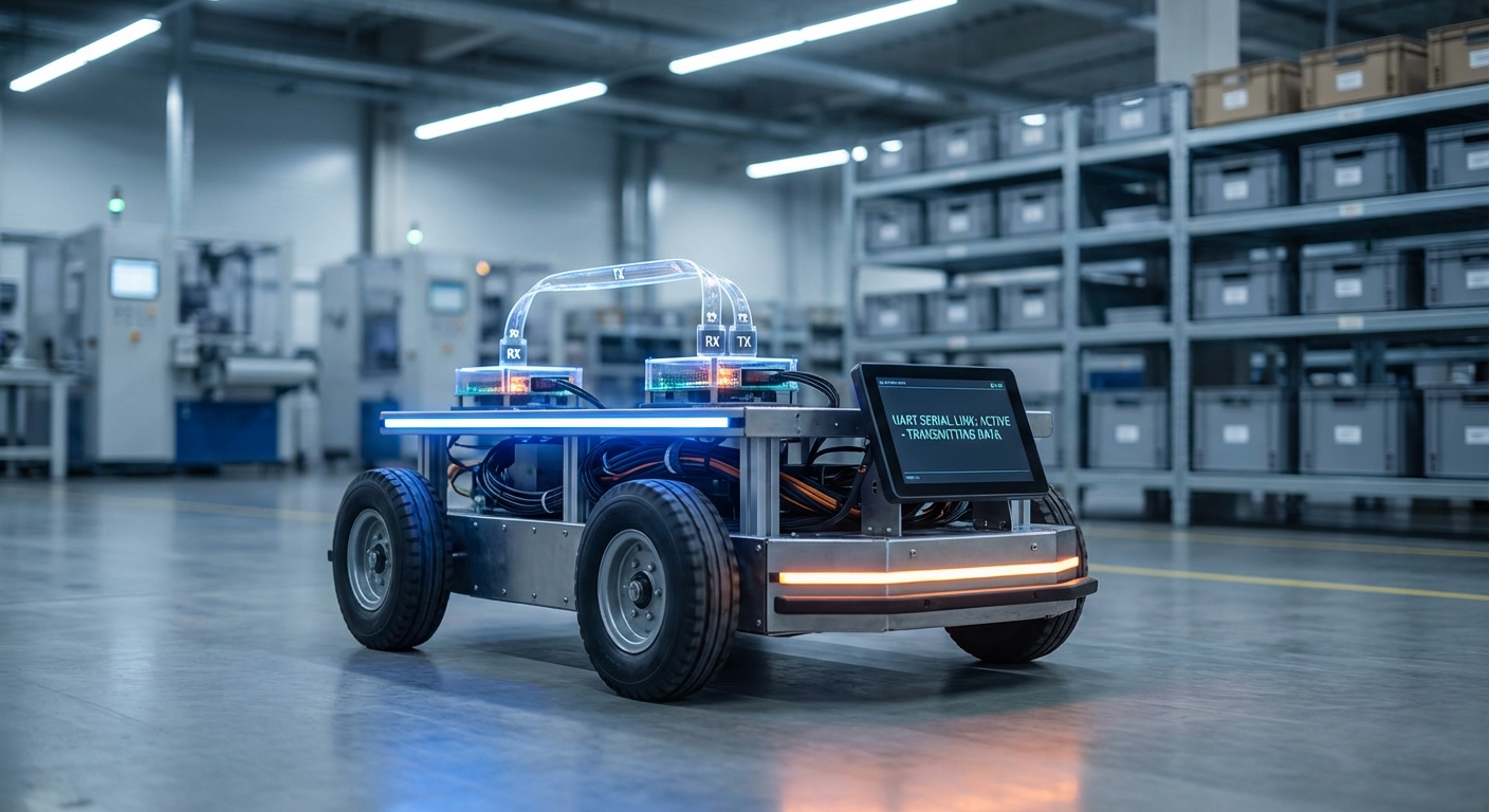
UART Serial Communication
Universal Asynchronous Receiver-Transmitter (UART) is the fundamental nervous system of modern AGVs, bridging the gap between high-level navigation processors and low-level actuators. It ensures reliable, point-to-point data transmission essential for precise motor control and sensor integration.
Core Concepts
Asynchronous Timing
Unlike SPI or I2C, UART requires no shared clock signal. Instead, both devices agree on a specific timing speed (baud rate) beforehand to synchronize data interpretation.
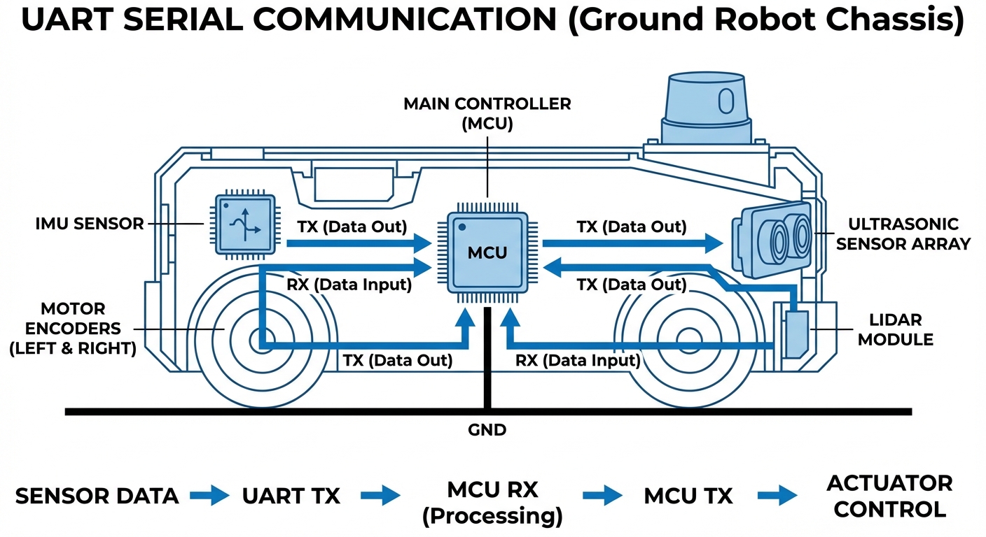
TX & RX Lines
Communication relies on two wires: Transmit (TX) and Receive (RX). The TX pin of the AGV's controller connects directly to the RX pin of the peripheral, creating a cross-coupled link.
Baud Rates
Speed is critical. Standard rates like 9600 or 115200 bps determine how fast navigation data travels. Mismatched rates result in gibberish data and potential robot errors.
Data Integrity
To ensure commands aren't corrupted in noisy factory environments, UART frames often include parity bits to check for errors before executing movement logic.
Start & Stop Bits
Since there is no clock, start and stop bits frame the data packet. These bits define the boundaries of the character being transmitted, ensuring the receiver knows when to read.
Full Duplex
UART allows for full-duplex communication, meaning an AGV can transmit velocity commands while simultaneously receiving odometer readings from the wheels.
How It Works: The Data Stream
At a hardware level, UART acts as a translator between the parallel data bus of the robot's CPU and the serial transmission line. When the navigation computer decides to move forward, it sends a byte of data to the UART transmitter in parallel.
The UART hardware contains a shift register that takes this byte and pushes it out one bit at a time (serially) over the TX wire. The sequence begins with a 'Start Bit' (pulling the line low) to wake up the receiver.
On the receiving end—such as a motor driver—the process is reversed. The receiver samples the line at the agreed-upon baud rate, reconstructs the byte in its own shift register, and triggers an interrupt to process the movement command immediately.
Real-World Applications
LiDAR & Sensor Modules
Many 2D LiDAR units used for SLAM (Simultaneous Localization and Mapping) output point cloud data via high-speed UART interfaces. This allows the main computer to construct a map of the warehouse in real-time.
Motor Control Units (MCUs)
Dedicated motor drivers often communicate via UART. The main CPU sends velocity vectors and PID tuning parameters, while the driver reports back current draw, temperature, and encoder ticks.
Wireless Telemetry
Bluetooth, Zigbee, and LoRa modules typically interface with the robot via UART. This enables fleet management software to send route updates wirelessly to the AGV without heavy networking overhead.
Diagnostics & Debugging
The "Console Port" on almost every embedded Linux robot is a UART interface. Technicians use this simple serial connection to access the root shell, view boot logs, and troubleshoot hardware failures in the field.
Frequently Asked Questions
What is the difference between UART, I2C, and SPI in robotics?
UART is asynchronous, point-to-point, and uses two wires without a clock, making it ideal for longer distances and device-to-device comms. I2C is a multi-master bus good for connecting many slow sensors on one board. SPI is a high-speed synchronous protocol used for fast peripherals like displays or SD cards over short distances.
How far can a UART signal travel reliably?
Standard TTL-level UART is generally reliable only over short distances, typically less than 1 meter (3 feet), due to signal degradation and noise susceptibility. For longer distances in a robot chassis, it is standard practice to convert UART to RS-232 or RS-485 differential signaling, which can travel hundreds of meters.
What happens if the baud rates are mismatched?
If the transmitter and receiver operate at different speeds (e.g., 9600 vs 115200), the timing of the bits will misalign. The receiver will sample the line at the wrong moments, resulting in framing errors and corrupted data (often appearing as random garbage characters), causing communication failure.
What is Hardware Flow Control (RTS/CTS) and do I need it?
RTS (Request to Send) and CTS (Clear to Send) are extra wires used to prevent buffer overflows. If the receiving robot processor is busy, it toggles the RTS line to tell the sender to pause. This is crucial for high-speed data transfer, such as downloading large map files or firmware updates to a module.
Can I connect a 5V sensor to a 3.3V Microcontroller UART?
Directly connecting them often damages the 3.3V pin. You must use a Logic Level Converter (shifter) or a voltage divider circuit on the RX line of the 3.3V device. However, some modern microcontrollers (like certain STM32 inputs) are "5V tolerant," but you should always verify the datasheet first.
How do I troubleshoot UART issues on an AGV?
Start by verifying the baud rate settings on both ends. Use a USB-to-TTL serial adapter (like FTDI) to "sniff" the TX and RX lines using a computer terminal. An oscilloscope or logic analyzer is the best tool to verify signal integrity, ensuring the square waves are clean and the voltages are correct.
What is Software Serial vs Hardware Serial?
Hardware Serial uses dedicated physical circuits within the microcontroller to handle timing, freeing up the CPU. Software Serial ("bit-banging") emulates UART using code and standard GPIO pins. Software Serial is CPU-intensive and less reliable at high speeds, so Hardware Serial is always preferred for robotics.
Is UART suitable for safety-critical stop commands?
While UART is reliable, it is not inherently fail-safe like a dedicated E-Stop hardware loop. For safety-critical functions, UART commands should be accompanied by checksums (CRC) to detect corruption, and the system should have a timeout mechanism (watchdog) to stop the robot if the data stream is lost.
Can I daisy-chain multiple devices on one UART line?
No, standard UART is strictly point-to-point (one sender, one receiver). To connect multiple devices to a single bus, you must use a different protocol like RS-485 (which is UART-based but electrical different) or use a hardware multiplexer to switch between devices.
How does UART handle parity errors?
The UART hardware sets a flag when a parity error is detected. It does not automatically request a re-transmission. It is up to the software layer (your robot's firmware) to check this flag and request the data packet again if an error occurs.
What is the maximum speed (baud rate) for UART?
While 115200 is common, modern microcontrollers can support baud rates up to several Mbps (e.g., 3 Mbps or higher). However, as speed increases, the physical wiring must be shorter and better shielded (twisted pair) to prevent capacitance from rounding off the signal edges.