SPI Interface
Unlock high-speed, synchronous communication between microcontrollers and sensors. The Serial Peripheral Interface (SPI) is the backbone of real-time data transmission in modern AGVs, ensuring zero-latency control loops for precision navigation.

Core Concepts
Synchronous Clock
SPI uses a dedicated clock line (SCLK) generated by the master, ensuring perfect synchronization between the robot's CPU and peripherals without start/stop bits.
Master-Slave Architecture
A single "Master" device (your main AGV controller) controls one or more "Slave" devices (IMUs, drivers), simplifying data flow logic.
Full Duplex
Data can be sent and received simultaneously. While the AGV sends a motor command, it can instantly receive encoder feedback in the same clock cycle.
High Throughput
Capable of speeds in the MHz range (often 10MHz to 50MHz+), SPI is significantly faster than UART or I2C, ideal for heavy data streams like LIDAR.
4-Wire Logic
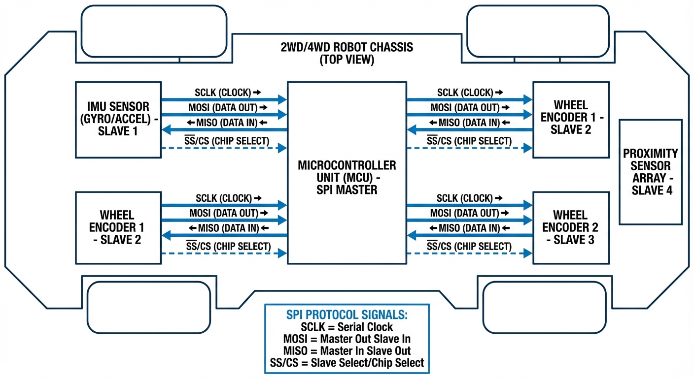
Utilizes four distinct lines: MOSI (Master Out Slave In), MISO (Master In Slave Out), SCLK (Clock), and SS/CS (Slave Select) for robust hardware control.
Short Range
Designed for onboard communication. In robotics, SPI is used strictly within the PCB or short cable runs to minimize signal degradation and noise.
How It Works: The 4-Wire Exchange
In an AGV architecture, the microcontroller (Master) initiates communication by pulling the Chip Select (CS) line low for a specific target device, such as a gyroscope. This alerts the specific peripheral that data is incoming.
The Master then generates clock pulses on the SCLK line. With every clock pulse, a bit of data is shifted out on the MOSI line to the sensor, while simultaneously, a bit of data is shifted in from the sensor on the MISO line.
This "shift register" approach allows for incredible speed. Unlike asynchronous protocols that need overhead for start/stop bits and parity, SPI dedicates every clock cycle to raw data payload. For a robot balancing on two wheels or navigating a crowded warehouse, this microsecond-level speed is non-negotiable.
Real-World Applications
Inertial Measurement Units (IMUs)
AGVs rely on IMUs for orientation and acceleration data. SPI allows the main CPU to poll accelerometers and gyroscopes at rates exceeding 1kHz, enabling stable self-balancing and smooth turning arcs.
High-Resolution Encoders
Absolute magnetic encoders used in robotic arms or precision wheels often use SPI. This provides instant position feedback without the latency associated with pulse-counting methods, essential for picking and placing accuracy.
TFT/LCD Displays
Human-Machine Interfaces (HMIs) on mobile robots require high data bandwidth to refresh screens. SPI drives these displays efficiently, allowing the robot to show status, battery levels, and error codes in real-time.
Black Box Data Logging
Writing logs to SD cards is a classic SPI application. Robots can record sensor data, pathing decisions, and error logs to an onboard SD card at high write speeds for post-operation diagnostics.
Frequently Asked Questions
What is the main difference between SPI and I2C for robotics?
The primary difference is speed and wiring complexity. SPI is significantly faster (often 10MHz+) and supports full-duplex communication, making it better for high-bandwidth sensors like IMUs. I2C is slower (usually 100kHz or 400kHz) and half-duplex but requires only two wires, making it better for simple sensors or when pin count is limited.
What is the maximum reliable cable length for SPI?
SPI is intended as an on-board protocol. Reliable transmission usually degrades after 10-20cm depending on clock speed and capacitance. For connecting distinct modules across a large AGV (e.g., >30cm), you should use differential signaling (RS-485) or CAN bus, or use SPI buffers/extenders cautiously.
How many slave devices can I connect to one SPI bus?
Theoretically, the limit depends on the number of available GPIO pins on your Master microcontroller to act as Chip Select (CS) lines. Each slave requires its own CS line. Alternatively, you can daisy-chain devices if the hardware supports it, though this increases software complexity.
What are SPI Modes (CPOL and CPHA) and why do they matter?
There are 4 SPI modes (0-3) defined by Clock Polarity (CPOL) and Clock Phase (CPHA). This determines whether the clock idles high or low, and on which edge (rising or falling) data is sampled. You must match the Master's configuration exactly to the Slave device's datasheet, or communication will fail entirely.
Why is SPI preferred for motor drivers in AGVs?
SPI allows for detailed configuration and diagnostics beyond simple PWM control. With SPI, a robot controller can set current limits, micro-stepping modes, and decay settings on the fly, and read back error flags like over-temperature or stall detection instantly.
Can SPI handle 5V and 3.3V logic levels mixed?
No, direct connection is dangerous. If your MCU is 3.3V and a sensor is 5V (or vice versa), you need a logic level shifter. Connecting a 5V MISO line to a 3.3V MCU input can destroy the pin or the processor. Always verify voltage levels in your schematics.
What is "Daisy Chaining" in SPI?
Daisy chaining involves connecting the MISO of one slave to the MOSI of the next, creating a loop. This requires only one CS line for multiple devices. However, the data must pass through all devices like a shift register, which increases latency and is only supported by specific hardware.
How do I troubleshoot SPI communication failures?
A Logic Analyzer is the best tool. Check if the CS line drops low before the Clock starts. Verify the Clock speed isn't too fast for the slave. Ensure MISO and MOSI aren't swapped (a common error). Finally, check for ground loops or loose connections if data is intermittent.
Does SPI have error checking?
Native SPI does not have built-in error checking (like CRC in CAN bus) or acknowledgement bits (like in I2C). If data integrity is critical, you must implement a checksum or CRC validation protocol in your software layer on top of the raw SPI data.
Is SPI susceptible to electrical noise in industrial environments?
Yes, because it is single-ended (voltage referenced to ground) rather than differential. In a noisy factory environment with large motors, SPI lines should be kept extremely short, shielded, and routed away from high-power cables to prevent data corruption.
What is QSPI (Quad SPI) and do I need it?
Quad SPI uses 4 data lines instead of the standard 2 (MOSI/MISO) to transfer data 4x faster per clock cycle. It is primarily used for interfacing with external Flash memory or RAM in high-performance robotics controllers, but standard sensors usually stick to standard SPI.
Can I use DMA (Direct Memory Access) with SPI?
Absolutely, and it is recommended for robotics. Using DMA allows the microcontroller to transfer SPI data to memory in the background without occupying the CPU. This frees up the processor to calculate path planning or run safety algorithms while sensor data is being collected.