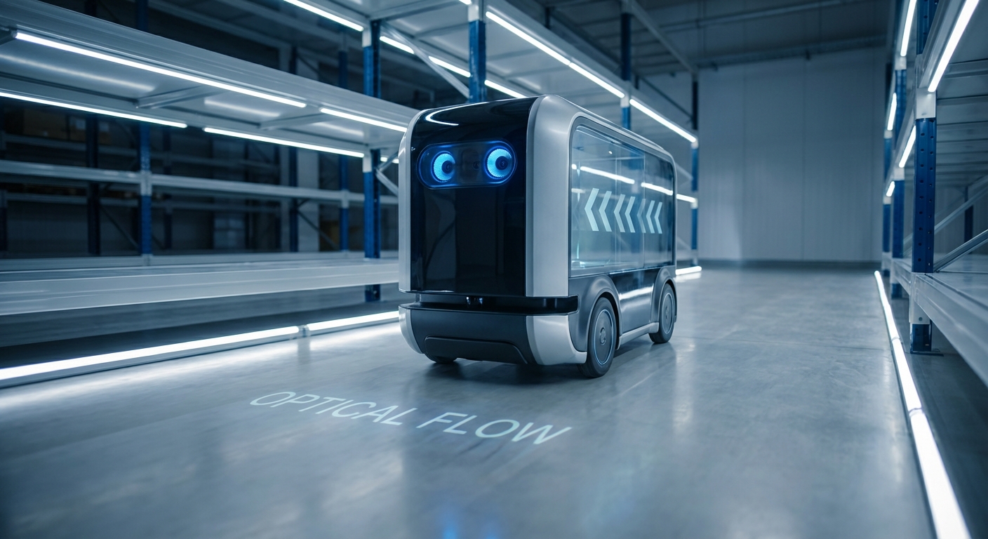
Optical Flow
Give your AGVs the ability to measure velocity and direction through visual perception. Optical flow creates a robust navigation layer that solves wheel-slip errors and enhances localization in GPS-denied environments.
Core Concepts
Pixel Motion Vectors
Calculates the apparent motion of brightness patterns between two consecutive image frames to determine velocity vectors $(u, v)$ for every pixel or feature.
Ego-Motion Estimation
Distinguishes the movement of the robot itself from the movement of objects in the scene, providing accurate relative positioning data without external beacons.
Sparse vs. Dense Flow
Robots can track specific feature points (Sparse/Lucas-Kanade) for speed, or analyze the entire image (Dense/Farneback) for higher detail but higher computational cost.
Brightness Constancy
Relies on the assumption that the intensity of a pixel on an object stays constant as it moves, allowing mathematical mapping of where that pixel went in the next frame.
Sensor Fusion
Often combined with IMU (Inertial Measurement Unit) data to correct for rotation-induced flow, isolating pure translational movement for better odometry.
Time-to-Contact (TTC)
By analyzing the expansion rate of the flow field (divergence), the robot can estimate how quickly it is approaching a surface without needing a depth map.
How It Works
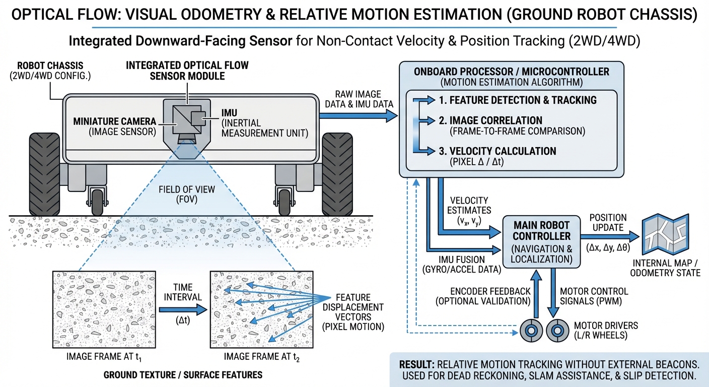
Optical flow sensors act as "visual odometers." Unlike wheel encoders, which measure the rotation of the wheel, optical flow measures the actual movement of the floor texture relative to the camera lens. This eliminates accumulated errors caused by wheels slipping on smooth concrete or uneven terrain.
The system typically employs a downward-facing camera. It captures a stream of images at high frequency. An algorithm (typically running on an edge processor or FPGA) compares Frame A to Frame B, identifying how textures have shifted $(dx, dy)$ in pixel space.
By knowing the camera's height and focal length, this pixel shift is converted into real-world velocity in meters/second. This data is fed into the robot's localization stack (like the Kalman Filter) to correct position estimates in real-time.
Real-World Applications
Warehouse Logistics
AGVs operating on polished concrete floors often experience wheel micro-slips during acceleration. Optical flow bridges the gap between wheel odometry and LiDAR localization, ensuring the robot doesn't "drift" between landmarks.
Precision Docking
When an AMR needs to dock with a charger or conveyor with millimeter precision, wheel encoders are insufficient. Optical flow provides the fine-grained velocity control needed for the final approach.
Outdoor Agriculture
In agricultural robotics, dirt and mud make wheel slippage inevitable. Optical flow uses the texture of the ground to maintain accurate heading and speed estimates despite poor traction.
Cleaning Robots
Industrial scrubbers wet the floor they drive on, drastically changing friction coefficients. Visual odometry via optical flow ensures the cleaning coverage map remains accurate even on wet surfaces.
Frequently Asked Questions
What is the main advantage of Optical Flow over Wheel Odometry?
The primary advantage is immunity to wheel slip. Wheel odometry calculates position based on wheel rotation, so if wheels spin on a wet spot or carpet, the robot thinks it moved when it didn't. Optical flow measures actual ground traversal, providing "truth" velocity data independent of traction.
Does Optical Flow work in the dark?
Generally, no. Standard cameras require ambient light to detect texture. However, many industrial optical flow sensors include an integrated IR (infrared) LED illuminator, allowing them to function perfectly in pitch-black environments by creating their own light source.
Does it require a textured surface?
Yes. Optical flow algorithms track texture patterns. Extremely glossy, uniform surfaces (like a pristine white whiteboard or glass) can cause the "Aperture Problem," where motion cannot be detected. In warehouse settings, scuffs, dust, and concrete aggregate usually provide sufficient texture.
How computationally expensive is it?
Dense optical flow is computationally heavy for a main CPU. However, modern robotics setups typically use dedicated sensors (like the PMW3901) or hardware acceleration (GPU/FPGA) to process flow calculations at the edge, sending only lightweight velocity data to the main navigation controller.
Can Optical Flow replace LiDAR?
No, they serve different purposes. LiDAR is primarily for mapping, obstacle avoidance, and global localization (knowing where you are on a map). Optical flow is for odometry (knowing how fast and how far you just moved). They are best used together in a sensor fusion setup.
What is the typical operating height?
It depends on the lens focal length. Standard "mouse sensor" style optical flow chips for robotics work best between 8cm and 30cm from the floor. Cameras with custom optics can work from much higher, such as drones flying at 50 meters, provided the surface texture is resolvable.
Does camera vibration affect accuracy?
Yes, significantly. Vibration can introduce "motion blur" or false movement signals. Optical flow sensors should be soft-mounted, or the data must be fused with a gyroscope (IMU) to mathematically subtract the rotational velocity caused by vibration from the translational velocity.
What is the "Aperture Problem"?
This occurs when looking at a moving edge through a small window (aperture). If you see a vertical line moving, you can't tell if it's moving purely sideways or diagonally. Robotics algorithms solve this by tracking corners (features with gradients in two directions) rather than just straight edges.
Is calibration required?
Yes. The system needs to know the exact distance from the camera to the floor and the lens parameters. If the height changes (e.g., due to suspension compression), the velocity scale will drift. Some advanced systems use a distance sensor (ToF) alongside the camera to dynamically scale the flow data.
How does it handle dynamic shadows?
Shadows moving across the floor can be interpreted as floor movement, causing error. Algorithms like Lucas-Kanade are susceptible to this, but modern robust methods and controlled lighting (using onboard LEDs and blocking external light) help mitigate shadow interference.