Odometry Calculation
Odometry is the fundamental process of estimating a robot's change in position over time using data from motion sensors. By integrating wheel velocity and steering angles, Autonomous Guided Vehicles (AGVs) can track their trajectory relative to a starting point with high precision.
Core Concepts
Wheel Encoders
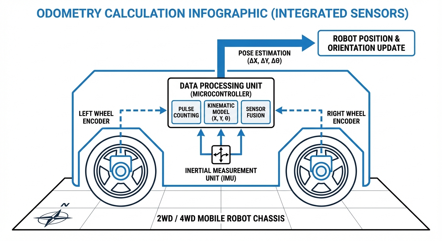
Rotary encoders attach to wheel motors to measure rotation. These raw tick counts are converted into linear distance and angular velocity for calculations.
Kinematic Models
Mathematical formulas representing the robot's physical constraints. Common models include Differential Drive (two wheels) and Ackermann (car-like) steering.
Dead Reckoning
The process of calculating current position based on a previously determined position. While essential, it is prone to cumulative errors over long distances.
Heading (Theta)
The orientation of the robot ($ \theta $) is as critical as X,Y coordinates. Even minute errors in heading calculation result in significant lateral position drift.
Sensor Fusion
Combining wheel odometry with IMUs (Inertial Measurement Units) to correct for wheel slippage, ensuring robust tracking on uneven surfaces.
Error Propagation
Understanding how small uncertainties in measurement scale up over time. Modern algorithms use covariance matrices to estimate confidence in the position.
How It Works
Odometry works by integrating velocity measurements over discrete time steps ($\Delta t$). For a differential drive robot, we measure the velocity of the left ($v_L$) and right ($v_R$) wheels independently.
The linear velocity ($v$) of the robot center is the average of the two wheel velocities, while the angular velocity ($\omega$) is determined by the difference between them, divided by the wheelbase length.
Using simple trigonometry, we update the robot's state vector $[x, y, \theta]$. The new position is calculated by adding the displacement ($v \cdot \cos(\theta)$ and $v \cdot \sin(\theta)$) to the previous coordinates. This continuous loop allows the AGV to "know" where it is relative to its start.
Real-World Applications
Warehouse Logistics
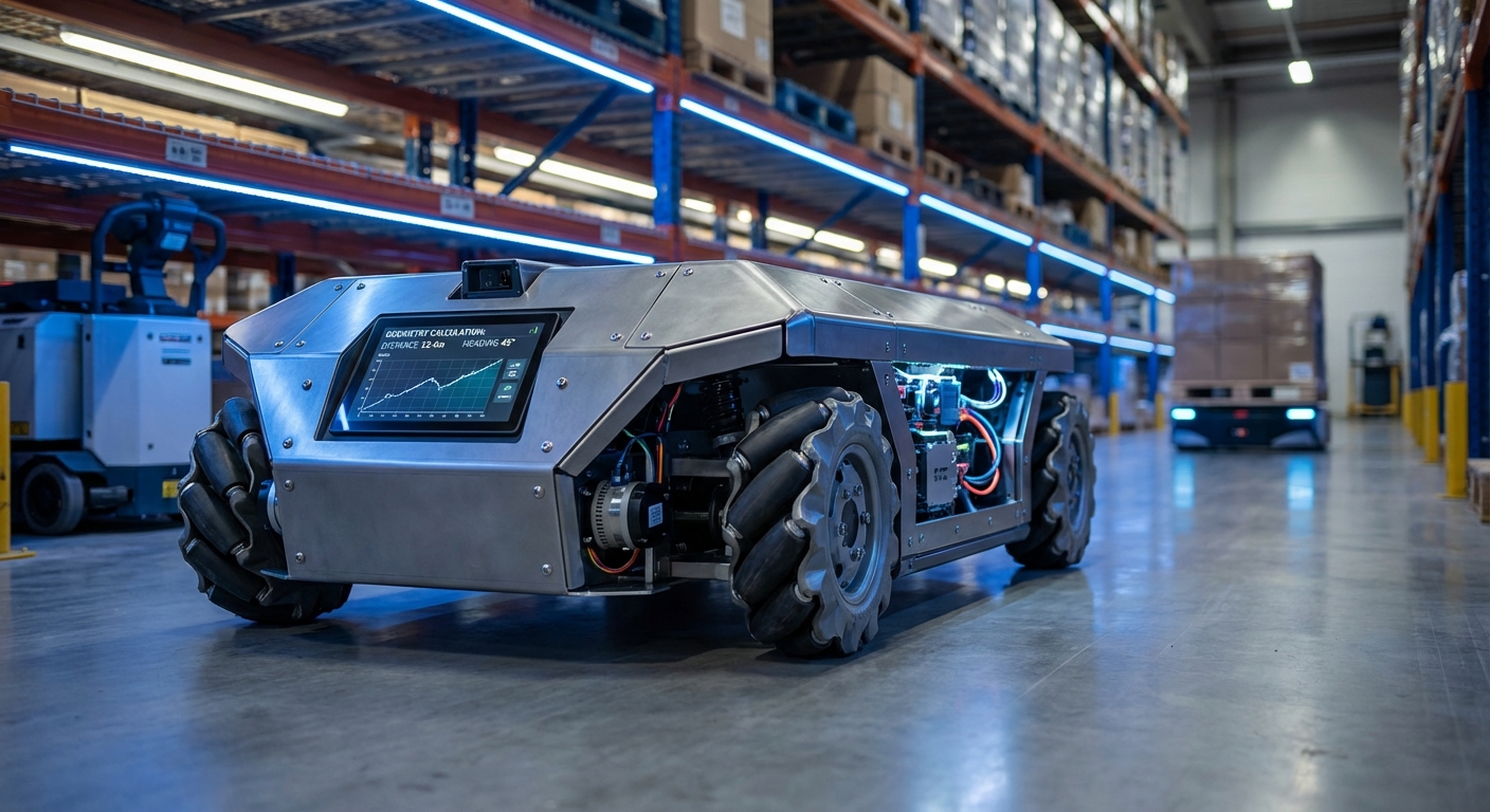
AGVs use odometry to navigate between rack aisles where GPS is unavailable. It bridges the gap between QR code markers or LIDAR localization scans.
Automated Manufacturing
Mobile manipulators rely on precise odometry to align with conveyor belts and assembly stations, ensuring sub-centimeter accuracy for material handoffs.
Healthcare Delivery
Service robots in hospitals utilize odometry to traverse long corridors autonomously, delivering linens and medicine without human intervention.
Clean Room Operations
In environments where floor markers are prohibited to maintain sterility, high-precision wheel odometry serves as the primary method for local navigation.
Frequently Asked Questions
What causes odometry drift in AGVs?
Drift is primarily caused by systematic errors (improper wheel diameter calibration, wheelbase measurement errors) and non-systematic errors (wheel slippage on slick floors, uneven terrain). Over time, these small errors accumulate, causing the estimated position to diverge from reality.
How is odometry different from SLAM?
Odometry provides a local, relative position estimate that is fast but drifts over time. SLAM (Simultaneous Localization and Mapping) uses external sensors like LIDAR or cameras to recognize landmarks and correct the odometry drift (loop closure), providing a global absolute position.
What is the role of an IMU in odometry?
An Inertial Measurement Unit (IMU) provides angular velocity data via gyroscopes. This is fused with wheel encoder data (typically using an Extended Kalman Filter) to provide a much more accurate heading estimate, especially when wheels slip during turns.
How often should odometry be calculated (Update Rate)?
For smooth navigation and control loops, odometry is typically calculated at 50Hz to 100Hz (every 10-20ms). Lower rates can result in "jagged" path estimation and poor control response, while higher rates may overburden the embedded processor without adding significant value.
Does tire wear affect odometry calculations?
Yes, significantly. As tires wear down, their diameter decreases. Since the algorithm assumes a constant diameter to convert rotations to distance, a worn tire will cause the robot to travel less distance than calculated. Periodic recalibration of wheel diameter parameters is essential.
What is the difference between differential and Ackermann odometry?
Differential odometry calculates motion based on the speed difference between two parallel drive wheels (like a tank). Ackermann odometry is used for car-like vehicles and relies on the steering angle of the front wheels and the velocity of the rear wheels, requiring different kinematic equations.
Can odometry work on 3D terrain (ramps)?
Standard 2D odometry assumes a flat plane ($x, y, \theta$). On ramps, the distance traveled along the slope is greater than the horizontal distance covered on the map. Without 3D IMU integration to account for pitch, 2D odometry will report incorrect X/Y coordinates on inclines.
How do we calibrate odometry parameters?
Calibration typically involves the "UMBmark" test or similar methods: driving the robot in a square path multiple times. By measuring the final offset from the start point, one can mathematically derive correction factors for wheel diameter and wheelbase width.
What encoder resolution is recommended?
Higher is generally better, but usually 500 to 2000 ticks per revolution is sufficient for industrial AGVs. Low resolution leads to quantization errors at low speeds, making velocity estimation noisy and affecting precise docking maneuvers.
Is Visual Odometry better than Wheel Odometry?
Visual Odometry (using cameras) is immune to wheel slip but requires good lighting and texture in the environment. Wheel odometry is more robust in featureless corridors or dark areas. The best systems fuse both sources for maximum reliability.