Force-Torque Sensors
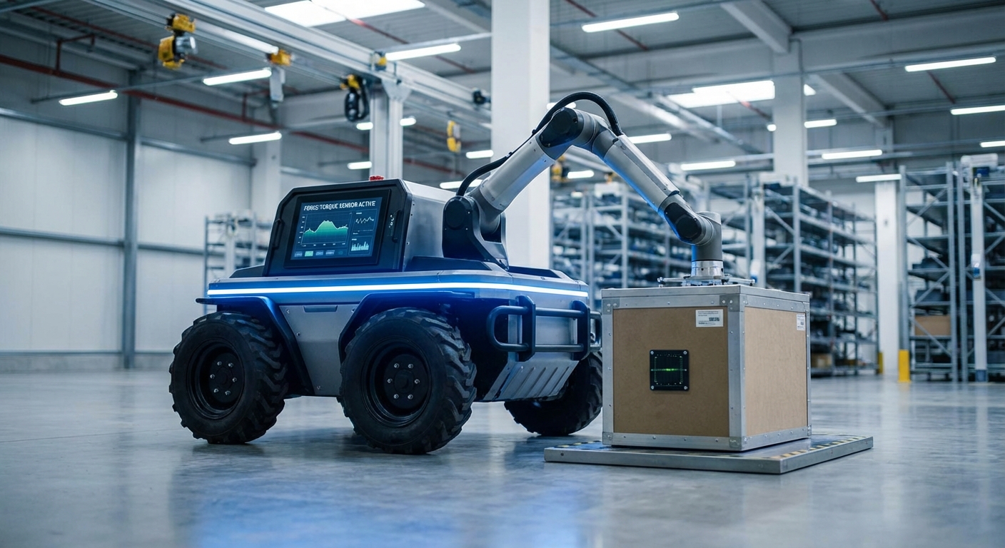
Force-Torque (F/T) sensors act as the central nervous system for interaction in mobile manipulators and AGVs, enabling precise feedback loops. By providing real-time data on six degrees of freedom, these sensors allow robots to feel their environment, ensuring safe collaboration and high-precision assembly.
Core Concepts
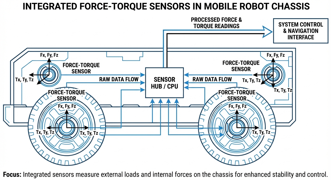
6-Axis Measurement
Measures forces (Fx, Fy, Fz) and torques (Tx, Ty, Tz) simultaneously. This full-spectrum data allows the robot to understand the exact vector and magnitude of contact.
Strain Gauge Tech
Utilizes metallic foil strain gauges bonded to a deformable structure. As the structure flexes under load, resistance changes are converted into digital force signals.
Compliance Control
Enables "active compliance," allowing the robot to relax its joints when pushing against a surface, preventing damage to the payload or the environment.
Collision Detection
Provides vastly superior sensitivity compared to motor current monitoring. F/T sensors detect unexpected impacts instantly, triggering emergency stops.
Digital Signal Processing
On-board electronics filter high-frequency noise and temperature drift, outputting clean data via EtherCAT, Modbus, or CAN bus directly to the controller.
Zero Gravity Mode
Allows for hand-guiding (lead-through programming). The sensor detects the operator's push and the robot moves accordingly, making programming intuitive.
How It Works
Force-Torque sensors are typically mounted between the robot flange and the end-effector (gripper). Structurally, they consist of a rugged transducer body housing sensitive strain gauges arranged in a Wheatstone bridge configuration. When external loads are applied to the tool, the transducer undergoes microscopic deformation.
This deformation changes the electrical resistance of the gauges. The internal electronics amplify this minute analog signal, filter out environmental noise, and convert it into a digital matrix representing forces along X, Y, Z axes and rotation around them.
In AGV mobile manipulation, this data acts as a feedback loop for the motion controller. If a mobile robot is inserting a battery pack, the F/T sensor ensures the insertion force never exceeds a safety threshold, adjusting the robot's trajectory in milliseconds to correct misalignment.
Real-World Applications
Precision Assembly
Mobile manipulators use F/T sensors for "search and insert" operations. For example, locating screw holes or snapping electronic connectors into place where vision systems might be occluded.
Sanding & Polishing
Robots maintain constant contact force against uneven surfaces. The sensor creates a feedback loop that adjusts the Z-axis depth in real-time to ensure a uniform finish regardless of surface curvature.
Palletizing & Stacking
Detecting the precise moment a box touches the pallet or stack. This eliminates the need for pre-programmed stack heights and accounts for crushed or uneven boxes automatically.
Medical Robotics
In hospital logistics AGVs or surgical assistants, F/T sensors provide the sensitivity required to handle biological samples or interact with patients without applying excessive pressure.
Frequently Asked Questions
What is the difference between a 3-axis and a 6-axis sensor?
A 3-axis sensor typically measures only the linear forces (Fx, Fy, Fz). A 6-axis sensor measures both linear forces and the rotational moments (Torques: Tx, Ty, Tz) around those axes. 6-axis sensors are essential for complex manipulation tasks where the robot needs to understand leverage and twisting motions.
How does an F/T sensor improve AGV safety?
Standard AGVs rely on LiDAR for navigation safety, but that doesn't help the robotic arm. F/T sensors provide "Power and Force Limiting" (PFL) capabilities. If the arm touches a human or obstacle, the sensor detects the force spike immediately and halts the robot, often faster than motor-current based detection.
What is impedance control vs. admittance control?
These are control strategies using F/T data. Impedance control makes the robot act like a spring-damper system (reacting to force by changing position). Admittance control measures the force and calculates a velocity setpoint. Admittance is typically used for stiff industrial robots, while impedance is common in lightweight cobots.
How often do F/T sensors need calibration?
Most modern optical or strain-gauge sensors are factory calibrated for life. However, it is standard practice to perform a "zeroing" operation via software at the start of a task to account for the weight of the end-effector (gripper). Recalibration is usually only needed after a severe crash or overload.
Are capacitive or optical sensors better than strain gauges?
Strain gauges are the industry standard for durability and cost. Optical sensors offer higher resolution and better immunity to electrical noise (EMI), making them ideal for MRI rooms or high-precision lab work. Capacitive sensors are less common in heavy industrial robotics due to hysteresis issues.
Can F/T sensors handle water and dust?
Yes, but you must check the IP rating. Many industrial F/T sensors are rated IP65 or IP67, meaning they are dust-tight and can withstand water jets or immersion. This is critical for AGVs operating in wash-down environments or dirty warehouses.
What communication protocols are supported?
EtherCAT, Ethernet/IP, and Modbus TCP are the most common for real-time industrial control. CAN bus is also popular in mobile robotics. For research and development (ROS-based systems), USB or Ethernet connectivity is standard.
How do I choose the right force range (Capacity)?
Calculate the static weight of your gripper and payload, plus the dynamic forces generated during maximum acceleration. A good rule of thumb is to select a sensor where your nominal load is 40-50% of the sensor's full scale to ensure high resolution while leaving headroom for accidental impacts.
Does the sensor affect the robot's payload capacity?
Yes. The sensor itself has weight, and it shifts the center of gravity of the tool flange slightly forward. You must subtract the sensor's weight from the robot's rated payload to determine the remaining capacity for the gripper and the part.
What is "Crosstalk" in F/T sensors?
Crosstalk occurs when a force applied on one axis (e.g., Fx) erroneously registers a reading on another axis (e.g., Fy or Tz). High-quality sensors use calibration matrices to mathematically compensate for this, keeping crosstalk typically below 1-2%.
Is ROS/ROS2 integration supported?
Generally, yes. Major manufacturers provide ROS packages (drivers) that publish `/wrench` topics containing the force and torque data. This makes integration into navigation stacks or MoveIt! manipulation planning relatively seamless.
What happens if the sensor is overloaded?
Most sensors have mechanical overload protection for up to 500-1000% of their rated capacity. However, extreme shock loads (like a high-speed crash) can permanently deform the sensing element, causing "zero drift" that cannot be fixed via software recalibration.